3D Scanning and Printing
Group Assignment
3D Printing
3D printing is the process of creating objects by depositing layers of material on top of each other. 3D printing is called additive manufacturing.
3D Printing Process
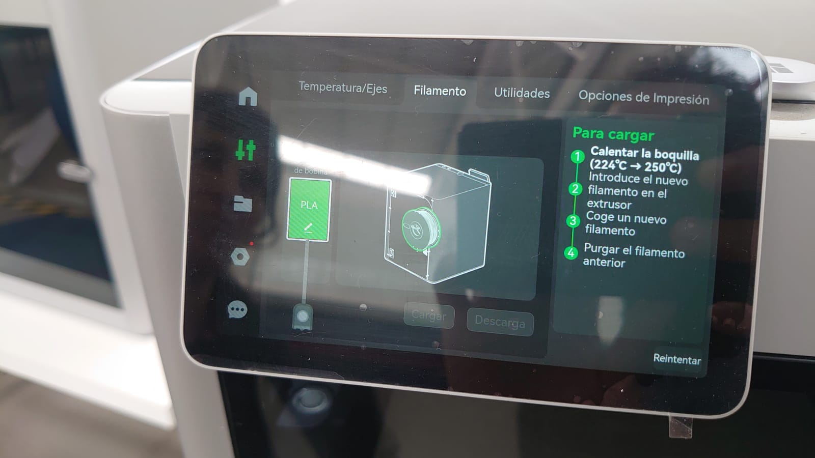
A 3D digital model is cut into hundreds of thin layers using specific software to export it in G-code format (Bambu Studio). This 3D printing format is a language that the 3D printer reads to know precisely when and where to deposit the material.
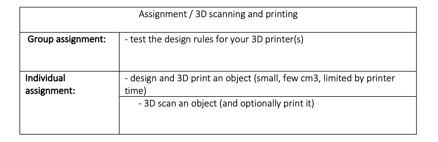
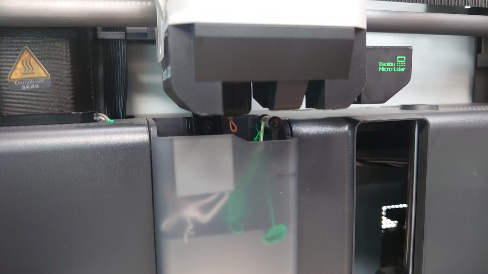
Material / filament / PLA Basic 1.75 mm Bambu Lab
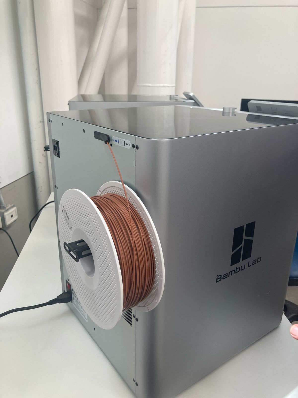
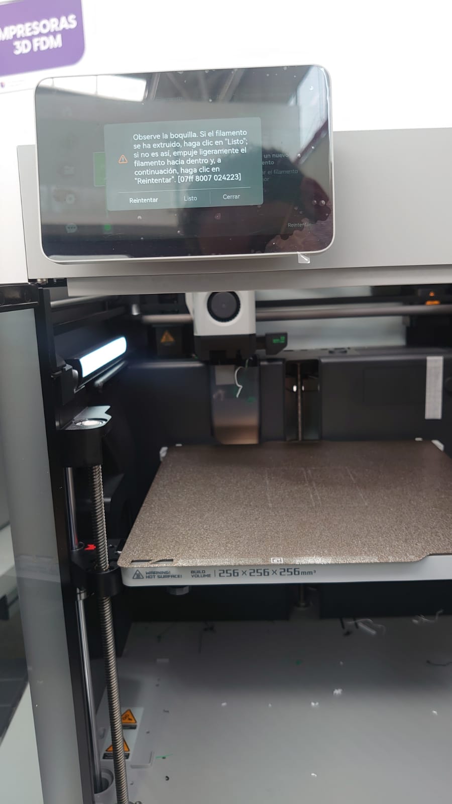
Printer Configuration
- Filament placement.
- Machine set up for filament reception.
- Control and printing of parts.
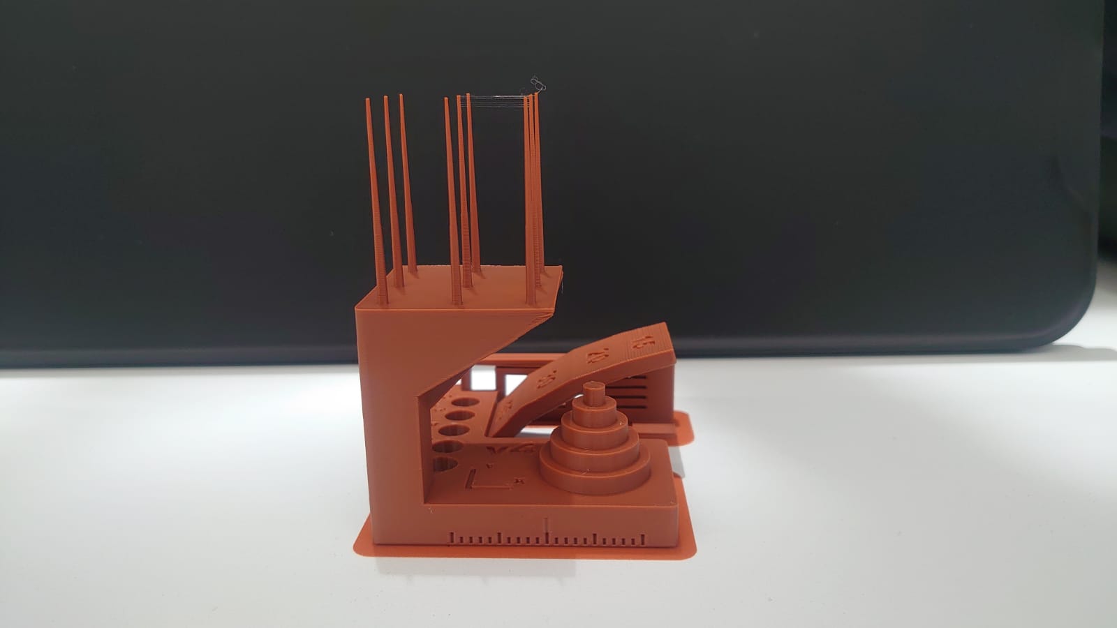
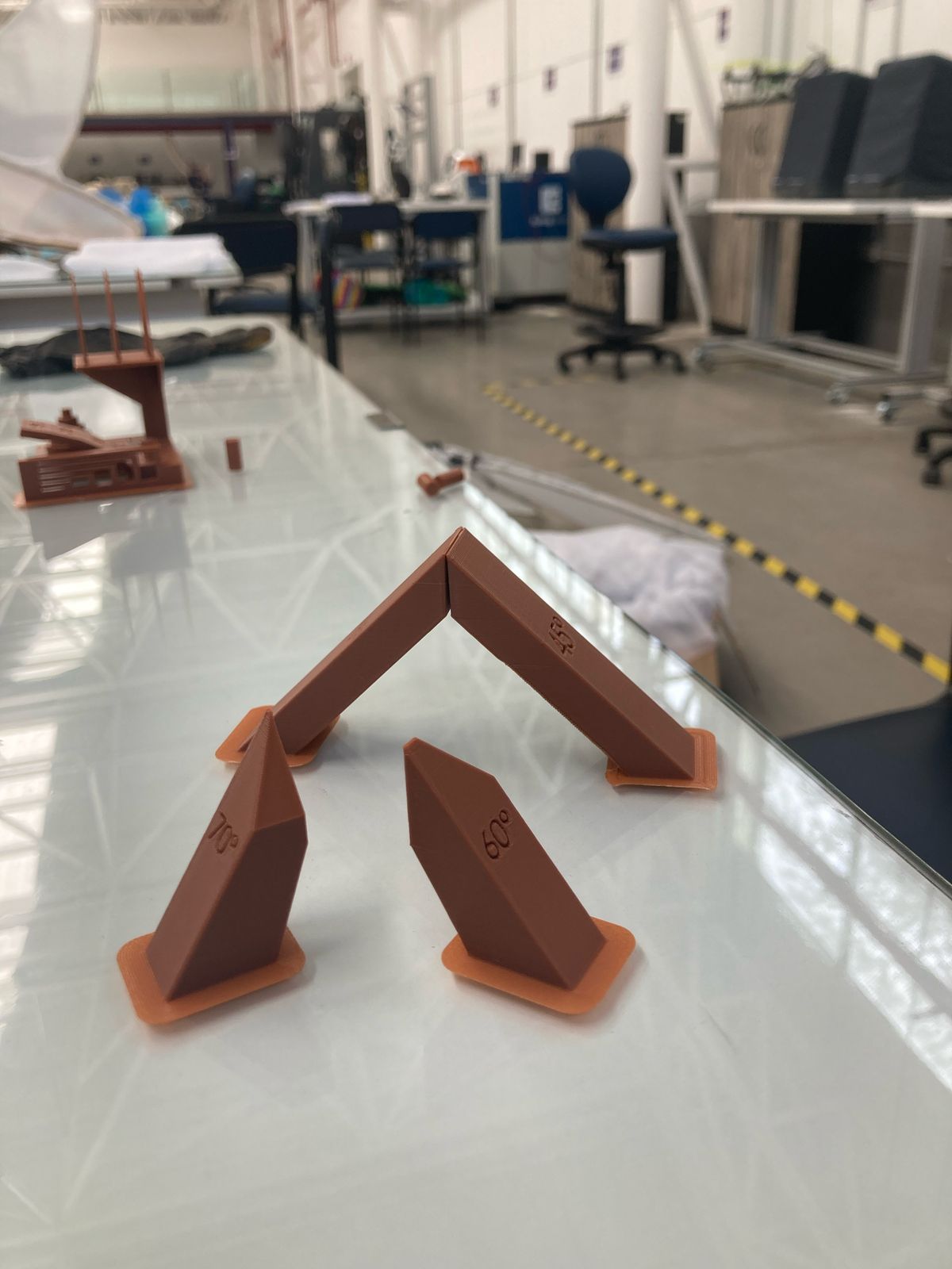
In the 3D printing research, some possibilities were identified, however, an existing practice was selected as it seemed to us very didactic to understand various processes of calibration for 3D printing. In this sense, the reference was taken from the following page: https://boingboing.net/2018/11/01/heres-a-test-print-to-make-s.html. In the practice we were able to identify:
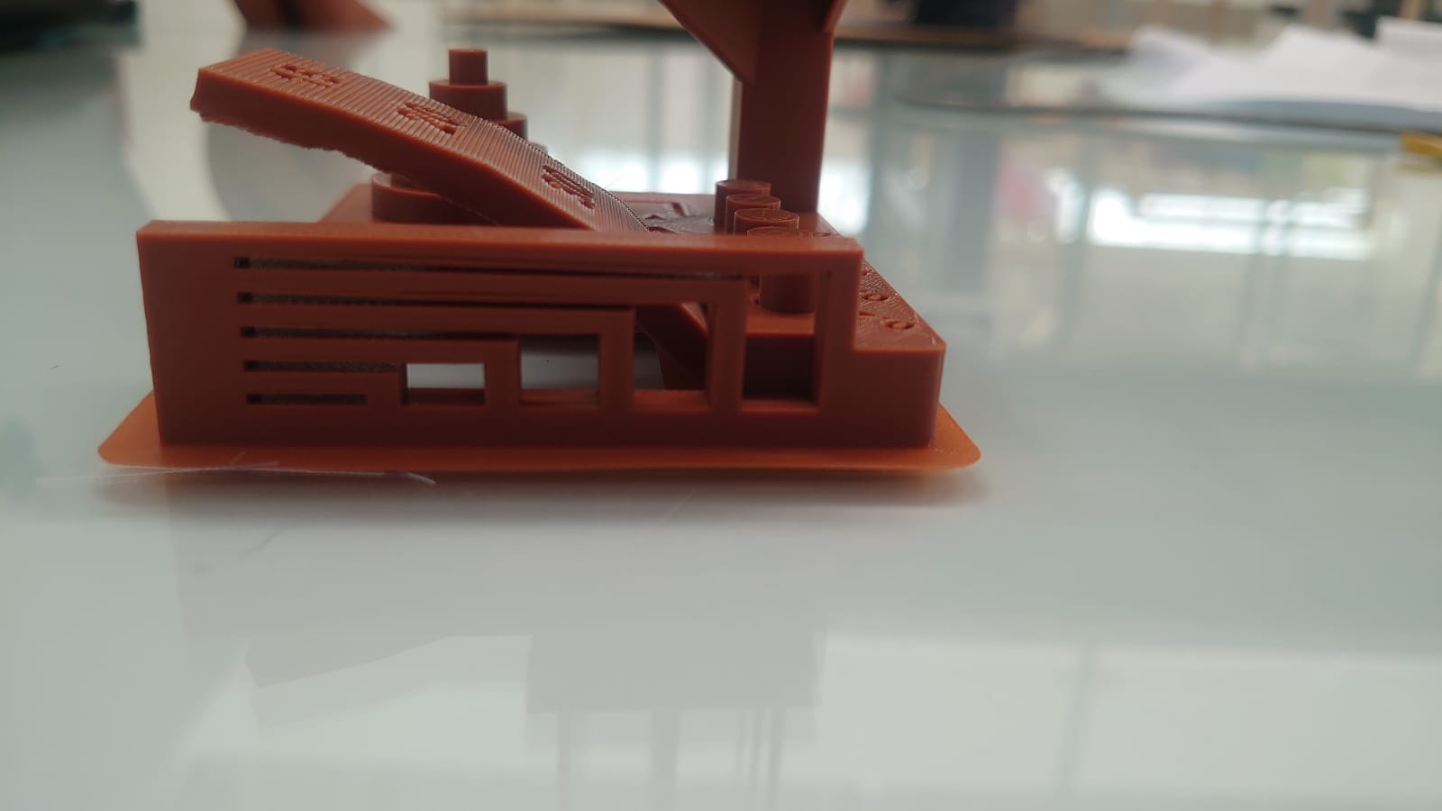
- Printing angles.
- Detail printing of overhangs.
- Conical prints to determine the quality of the detail and the transfer for printing by separate parts.
- Printing by tolerances.
- Printing at various levels, with different types of details.
- Overhang printed at 45 degrees without material support.
- The practice that is modeled on SolidWorks with different angles (45, 60, 70 degrees) of inclination, being additional to the practice taken as reference.
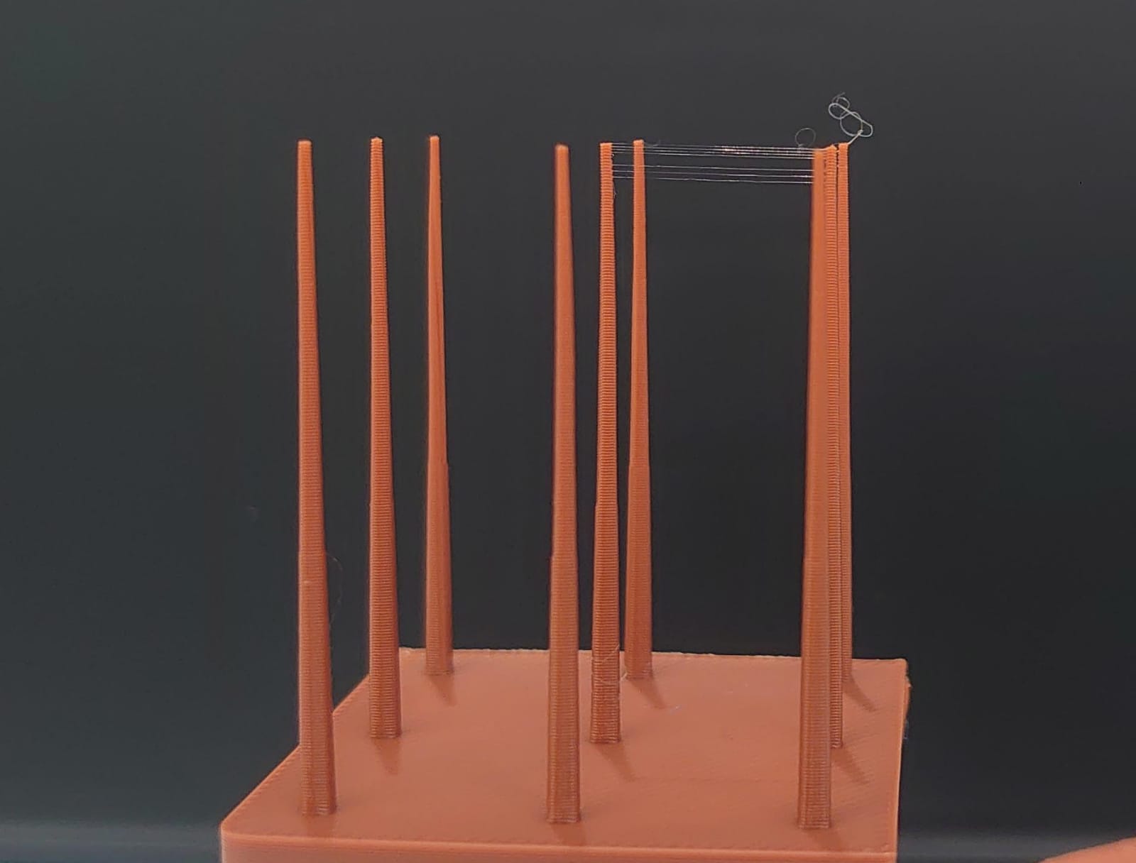
Conclusion
The printing quality maintains optimal configurations, since all the processes mentioned above were developed efficiently, which is reflected in the quality of the piece obtained. The only point to consider as a detail for the configuration of the calibrations is the transfer of the headset when extruding the filament, which provokes those filament recirculations between pieces, since there were inconveniences with the retraction.
Individual Practice
2D Modeling
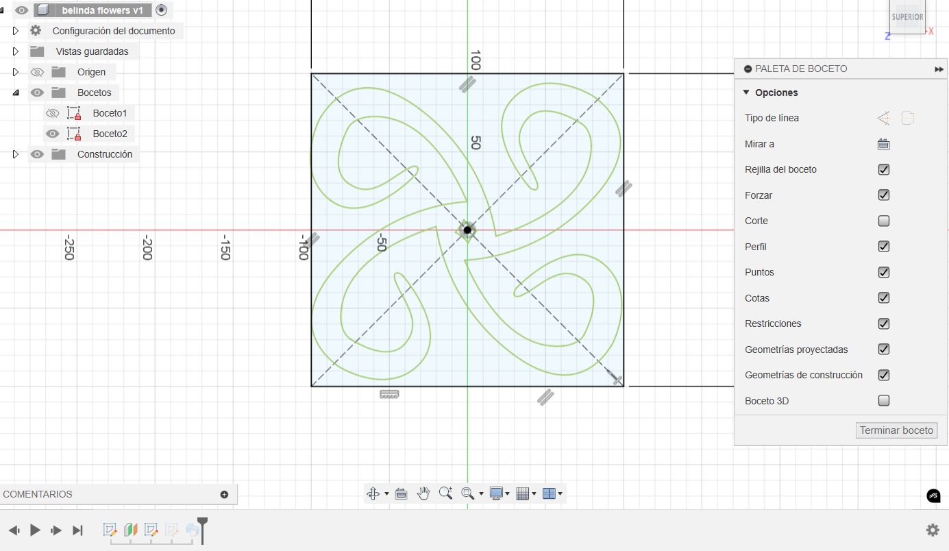
The two-dimensional conception of the figure was developed in Adobe Illustrator in order to obtain smooth curves by using vectors.
3D Modeling
The Adobe file was imported into Fusion 360 in order to obtain a three-dimensional figure.
- In a plane the figure was imported in SVG format, which is compatible with the 3D modeling program.
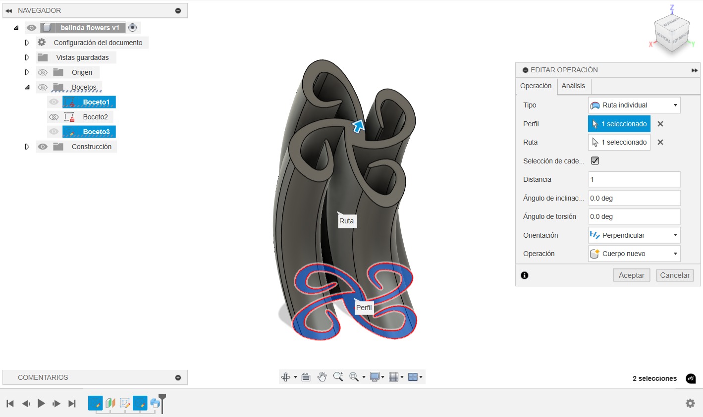
- A second plane at 14 cm was created to extrude the part.
- We import again the same SVG format to the second plane created.
- We create a plane-to-plane extrusion with torsion and inclination parameters in order to obtain a shape with motion perception.
We export the file as a point mesh in .STL (binary) format for better compatibility with the point mesh.
3D Printing
We used the Bambu Studio program, our own program for the existing machines in the laboratory.
Open the STL in Bambu Studio
Load the .STL file with the following settings:
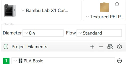
To begin, we select the printer we are going to use. In our case, the BAMBU LAB (X1 CARBON). Next, we will verify the choice of the printing surface according to the model we have, in our case, the TEXTURED PEI. Similarly, we verify that the diameter of our nozzle is adequate using the 0.4 mm nozzle. Finally, the appropriate material was selected. For this, we used the basic LAB bamboo PLA.
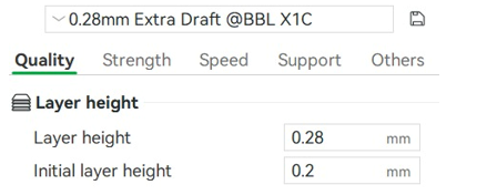
Among the configurations, we use those that come preconfigured by default by Bambu Studio, since they are the simplest and the ones that best fit our needs. The configuration is 0.28 Extra Draft. With this configuration, we will obtain a layer width of 0.28 mm, which will allow us to generate a good print quality with an appropriate speed for the test we are going to generate.
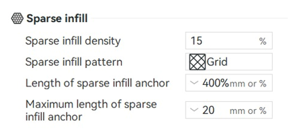
Within the program, it is possible to modify both the percentage of fill and the type of pattern used to fill the part, which will also allow us, depending on our needs, to increase or decrease the fill, being this case, being a test part with a 15% fill and a grid design, adequate.
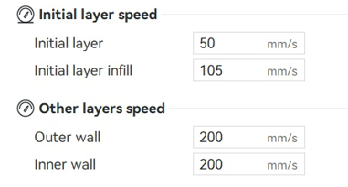
In addition, we have the option of adjusting the printing speed to ensure optimum quality. This function also allows us to set more efficient production times. In this case, we follow the program's recommendations, maintaining the same parameters for the initial and subsequent layers.
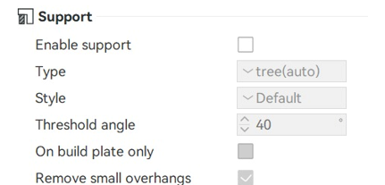
Since the design was made with specific details for its own configuration to be structured in its printing, the material supports were not enabled, which helps the part to be produced with greater speed.
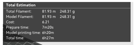
With all these parameters, the machine gives us a total of 248.31 grams of material, or 81.93 meters, which leads to an approximate time of 6 hours and 27 minutes.
3D Scanning
Scanning is a process that captures the shape of an object or environment to create digital models.
Prepare Object for Scanning
Login to the Scanning Programme
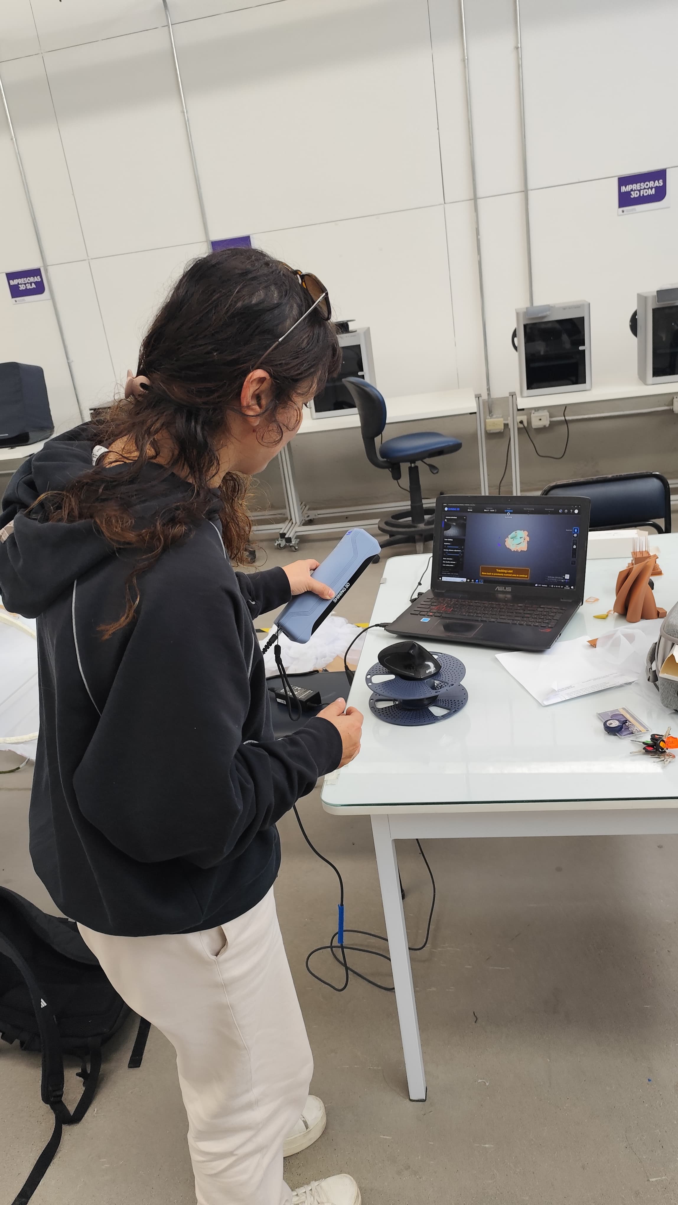
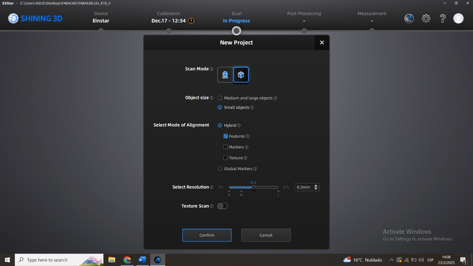
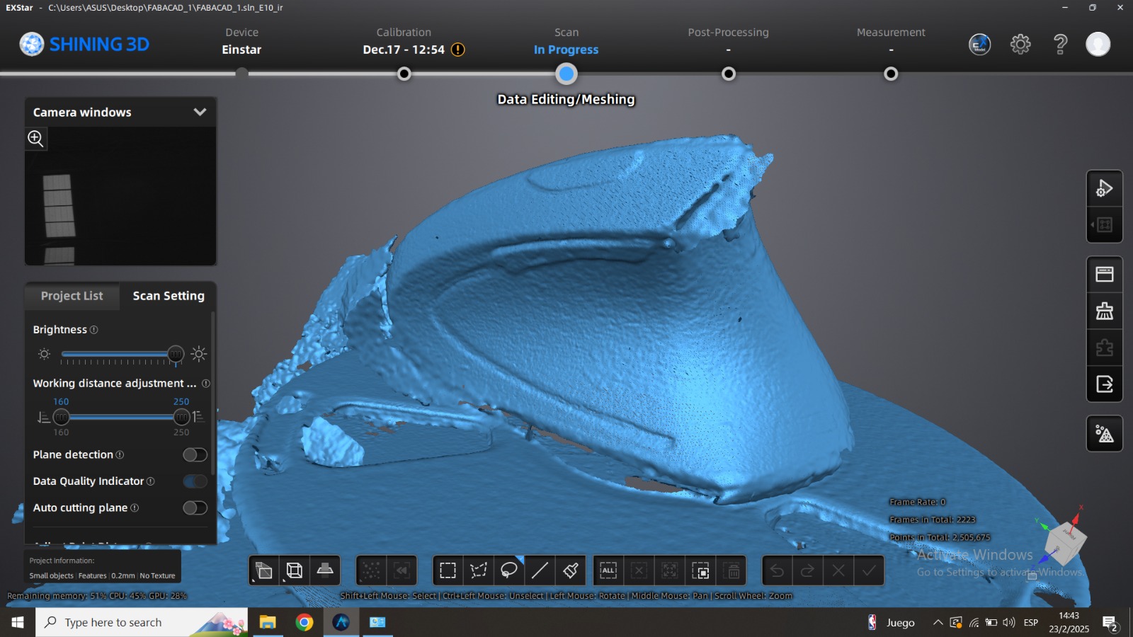
Perform the 3D Scan of the Object


Final Conclusions
The parameters used were of lower quality in order to reduce the printing time (approximately 6 hours). In spite of the complexity of the piece, given its inclination angles, the printing did not require support material.
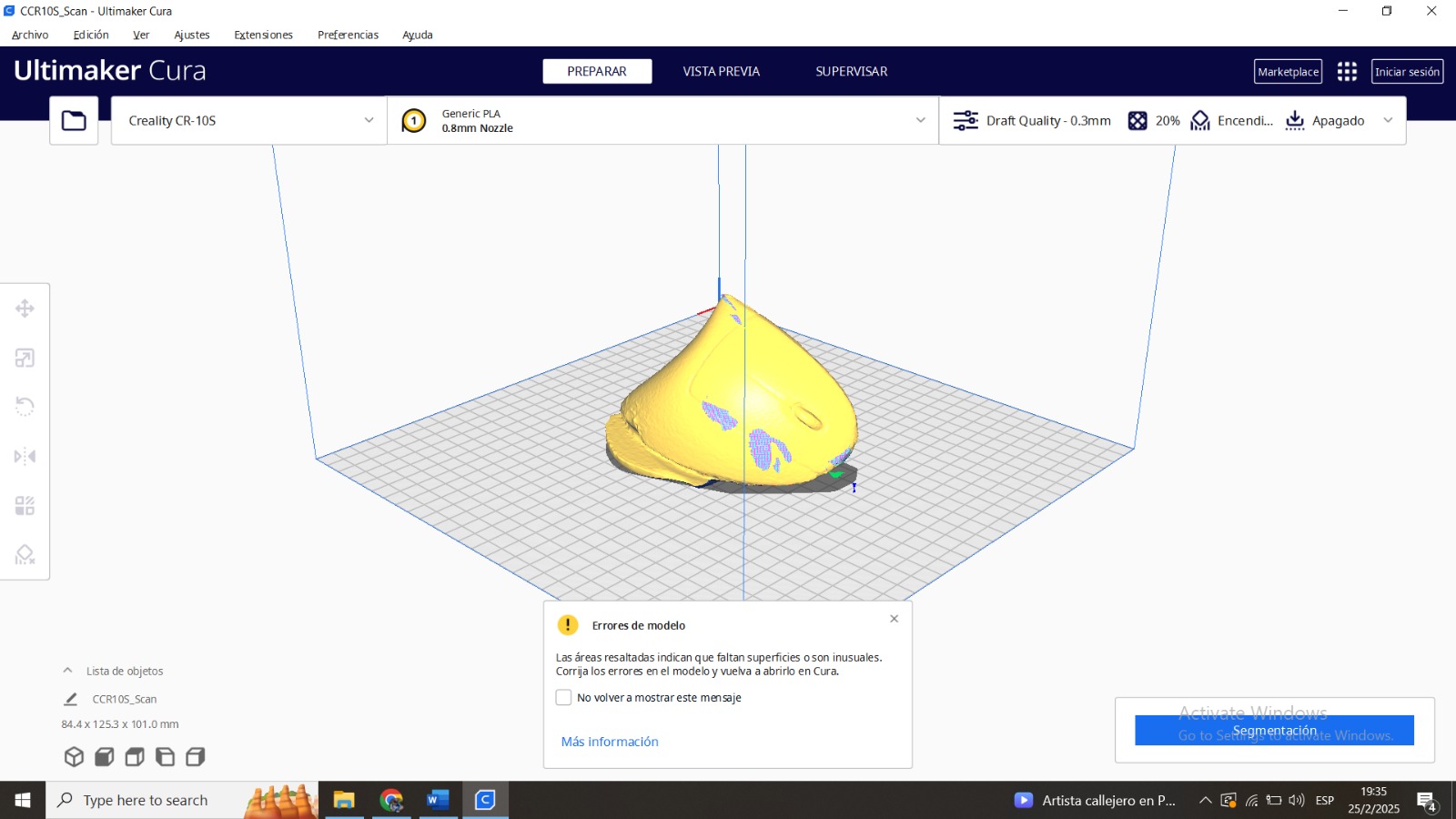
Scanning software repairs small gaps and simplifies scanning, making data more manageable in CAD.